Appearance
Tutorial: A Greenfield Project, End to End
Start with nothing. Finish with a drawing, a Bill of Materials and a CSV you can hand to procurement. This is the core ErgoPlanner flow — project → drawing → templates → agents → BoM.
Time required: 45–60 minutes Difficulty: Beginner to intermediate — no simulation knowledge needed Prerequisites: An account with the Engineer role or higher (see Account Setup)
What you will have at the end
- A project with a number, a client and a location
- A drawing with a pre-solved process area on it, placed from a template
- A Bill of Materials generated from that drawing, exported as CSV
If you are starting from drawings you already have — a DXF or DWG from your existing CAD system — do not follow this tutorial. Follow Brownfield: Starting From CAD Drawings You Already Have instead.
Part 1 — Create the project
Everything in ErgoPlanner hangs off a project: drawings, the BoM, the schedule, the stage gate. Create it first.
- Open Projects from the sidebar (
/admin/projects). - Click New project. The create form opens at
/admin/projects/new.
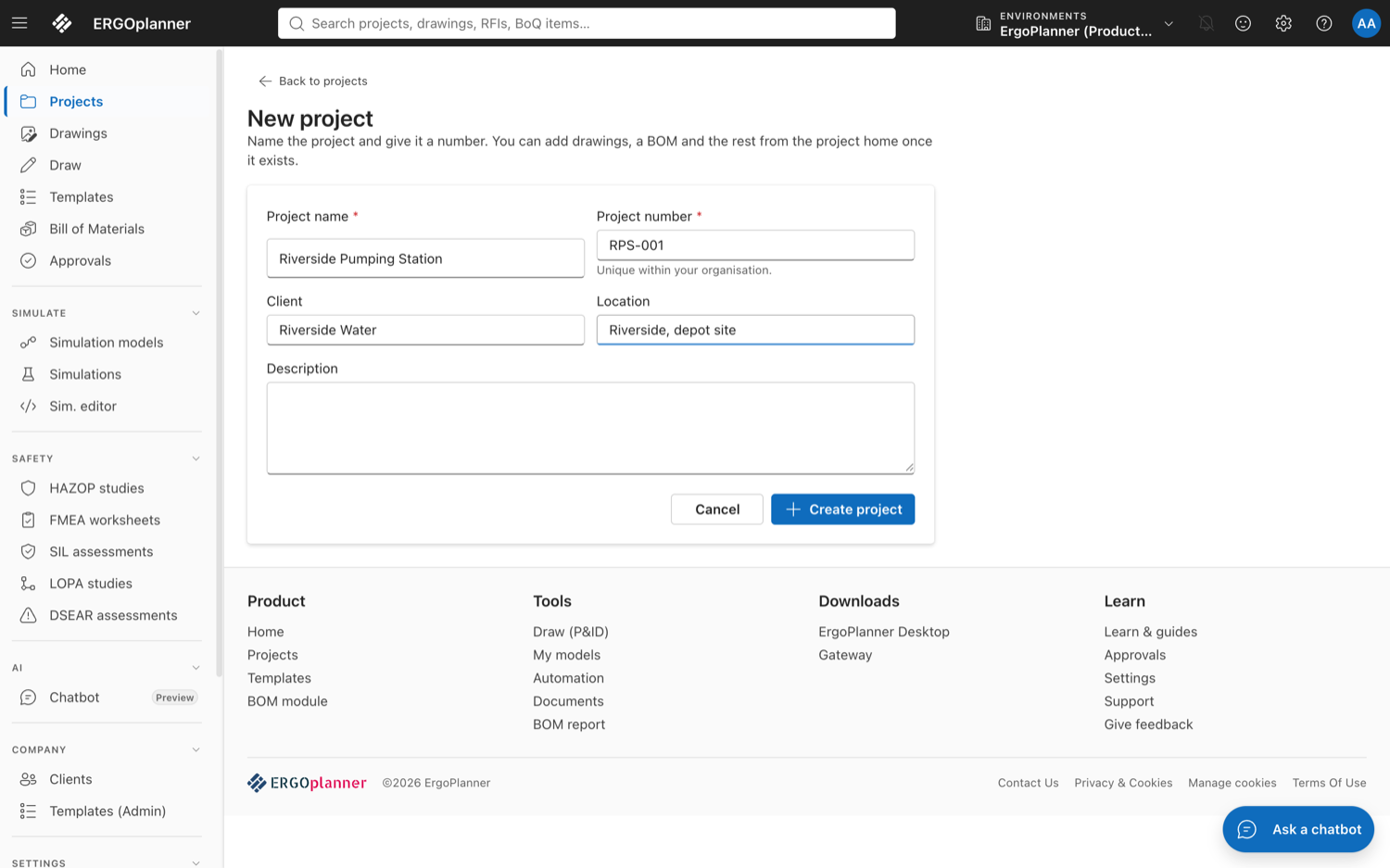
- Fill the form:
| Field | Required | Notes |
|---|---|---|
| Project name | Yes | Free text, up to 200 characters. e.g. Northfield pumping station upgrade |
| Project number | Yes | Must be unique within your organisation. e.g. PRJ-2026-014 |
| Client | No | Up to 200 characters. |
| Location | No | Up to 200 characters. |
| Description | No | Up to 2000 characters. |
- Click Create project. You land on the project's own page.
The project page carries the tabs you will come back to later — Overview, Engineering, Planning, Stage Gate, Design basis, Tags, Calculations and Carbon — plus the four stat cards (Total Assets, Open Issues, Milestone Progress, Team Members) and tables of the project's drawings, BoMs, documents and issues. All of them are empty right now. That is expected.
What you do not do here. There is no phase picker, no team-invitation step and no drawing-standard selection in the create form. Team membership is managed per organisation, and a project's lifecycle stage is managed afterwards on the Stage Gate tab (see A Revision Cycle).
Part 2 — Open a drawing
- Open the Draw page from the main navigation.
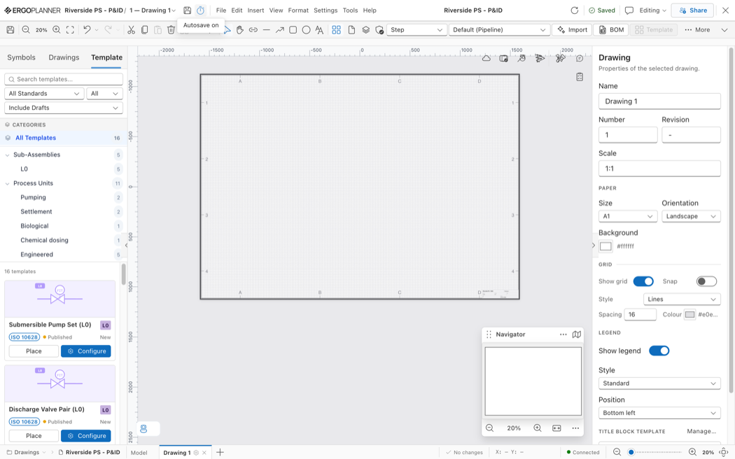
- With no drawing open you see the "No drawing open" screen. Click Create new drawing.
- In the Create new drawing dialog, enter a Drawing name and pick your new Project. Both are required; Create drawing stays disabled until the name is filled in.
- Expand "Drawing information (optional)" and fill in at least the Drawing number, Revision (
P01is the usual starting point) and Status (S0 — Work in progress). You will need these when you come to issue the drawing, and filling them now saves a trip back.
The full field list, the status codes and the discipline codes are in Creating a Drawing. Turn the autosave toggle on in the menu bar before you go any further.
Part 3 — Place a template
A drawing template is a pre-solved micro-P&ID: its symbols, its pipe routing, its instrumentation and its typed parameters, authored once and reused. Placing one is not AI redrawing your plant — the template is deep-copied with full fidelity and then its parameters adjust the duty count, the sizes and the options. See Drawing Templates Overview for how they are authored.
- In the left panel, switch to the Templates tab (the tabs are Symbols, Drawings, Templates).
- Find a template. You have four tools:
- Search templates… — free text across the library.
- Standard — filter by drawing standard.
- Level — filter by template level (0 = a single intelligent arrangement, 1 = a micro-P&ID, and up).
- Status — filter by publication state.
- The Categories tree below the filters.
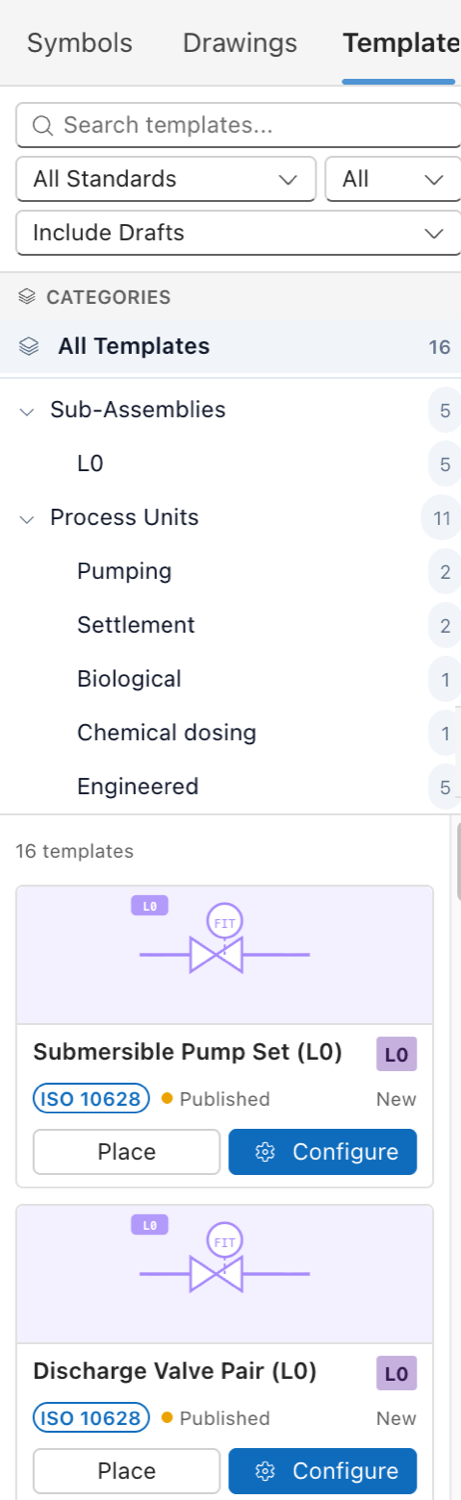
- Each template card carries two buttons:
| Button | What it does |
|---|---|
| Place | Places the template immediately, centred on the current viewport, with its default parameters. |
| Configure | Opens the parameter panel so you can set the parameters before placing. |
- Click Configure. The panel header reads Configure: template name, and below it is one field per parameter the template exposes — pump counts, design flows, pipe sizes, optional sections, instrument types. Each field enforces the template's own range; out-of-range values show an error and block placement.
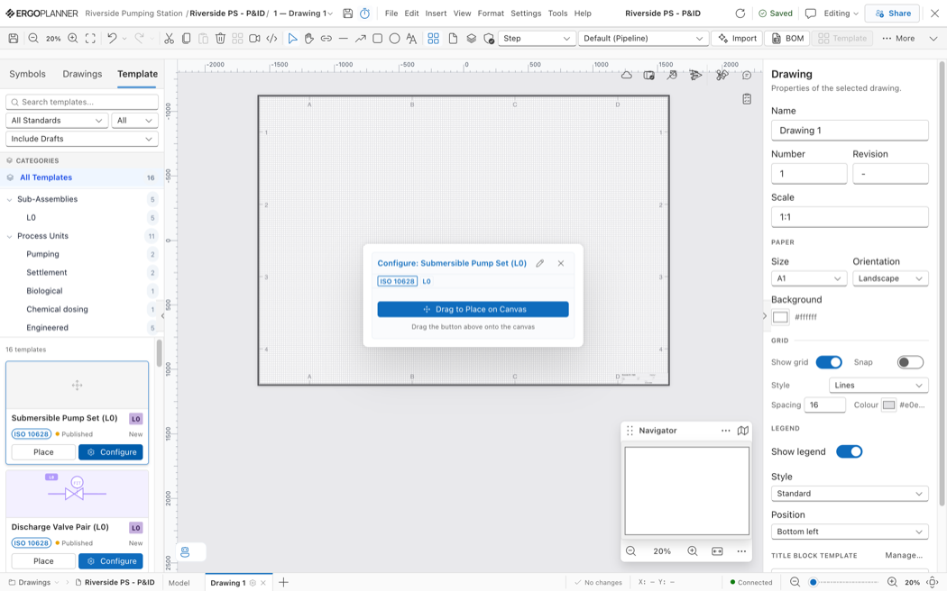
- Once the parameters validate, the panel shows Drag to Place on Canvas with the hint "Drag the button above onto the canvas". Drag that button to where you want the area to land and release.
The template's symbols, pipe runs and instruments appear as native, editable elements, with pipes routed and interface points connected as the template declares them.
Configure before you place. Parameters are applied at placement. There is no re-parameterise action on a template already on the canvas — to change
pump_countfrom 2 to 3, delete the placed group and place the template again with the new value. You can of course edit the resulting symbols and lines individually, like any other drawing content.
Repeat Part 3 for each process area you need. Then connect the areas to each other with the Connector tool (K) — see Drawing and Connecting.
Part 4 — Describe the process and let the AI compose it
Parts 2 and 3 are the manual route: you chose each template yourself. The AI Assistant does the same job from a sentence — it reads your description, searches your template library, and comes back with a staged plan you approve before anything touches the canvas.
In the Draw toolbar, click AI Assistant (the robot icon). The panel docks on the right.
If a warning bar reads "AI is not configured", stop here: no AI feature will answer until a SuperAdmin adds a provider key. See AI Provider Setup.
Type a description into the box at the bottom, or expand Example Prompts and click one. The shipped examples give you the register to aim for:
Create a sewage pumping station with two submersible pumps (duty/standby), wet well with level transmitter and float switches
Send it. For a description that names a sequence of process areas, the reply is a composition plan card, not prose. The card shows:
| Part of the card | What it tells you |
|---|---|
| Plan name and description | What the AI understood you to be asking for |
| A numbered stage per process area | The template chosen for it, and the parameters it will be placed with |
| Expand a stage | The template slug, every parameter and value, and which interface of which other stage it connects to |
| Gap rows, in amber | A stage with no matching template in your library |
| n warnings | Anything the planner wants to flag; click to expand |
0/n placed | The running count |
No screenshot: AI is not configured on the capture stack, so no composition plan could be generated honestly.
- Work the card before you place anything:
- Edit parameters (the cog on a stage) opens that stage's parameters as JSON for editing.
- Place this stage (the play icon on a stage) places just that one.
- On a gap row, choose Skip to drop it from the plan, Use stencil to draw it by hand from the symbol library, or Create to author a template for it.
- Click Place All. Stages are placed in order, with their interface points connected, and each one flips to Placed as it lands. When they are all down the footer reads All stages placed.
For a description of a single arrangement rather than a sequence, the reply is instead a set of template cards with a Place on canvas button each, or a generated diagram with an Add to Canvas button and badges counting its elements and connections.
What this is and is not. The plan is built from your template library — the AI's job is matching, parameterising and ordering, not inventing geometry. A process area with no template behind it comes back as a gap, by name, rather than as a guess.
Part 5 — What the agents contribute
ErgoPlanner has four agents you can dispatch. Open Agents from the sidebar (/admin/agents), pick one from the AI Agents list on the left, and talk to it:
| Agent | Shown as | What it does |
|---|---|---|
| Drawing agent | P&ID Designer | Places symbols, routes lines, generates tags |
| Planner agent | Planner | Works on a project programme — critical path on a schedule you hold, or a generated one |
| BoQ agent | Bill of Materials | Quantities and cost from your own rate cards |
| Simulation agent | Simulation | The process-simulation side of the product |
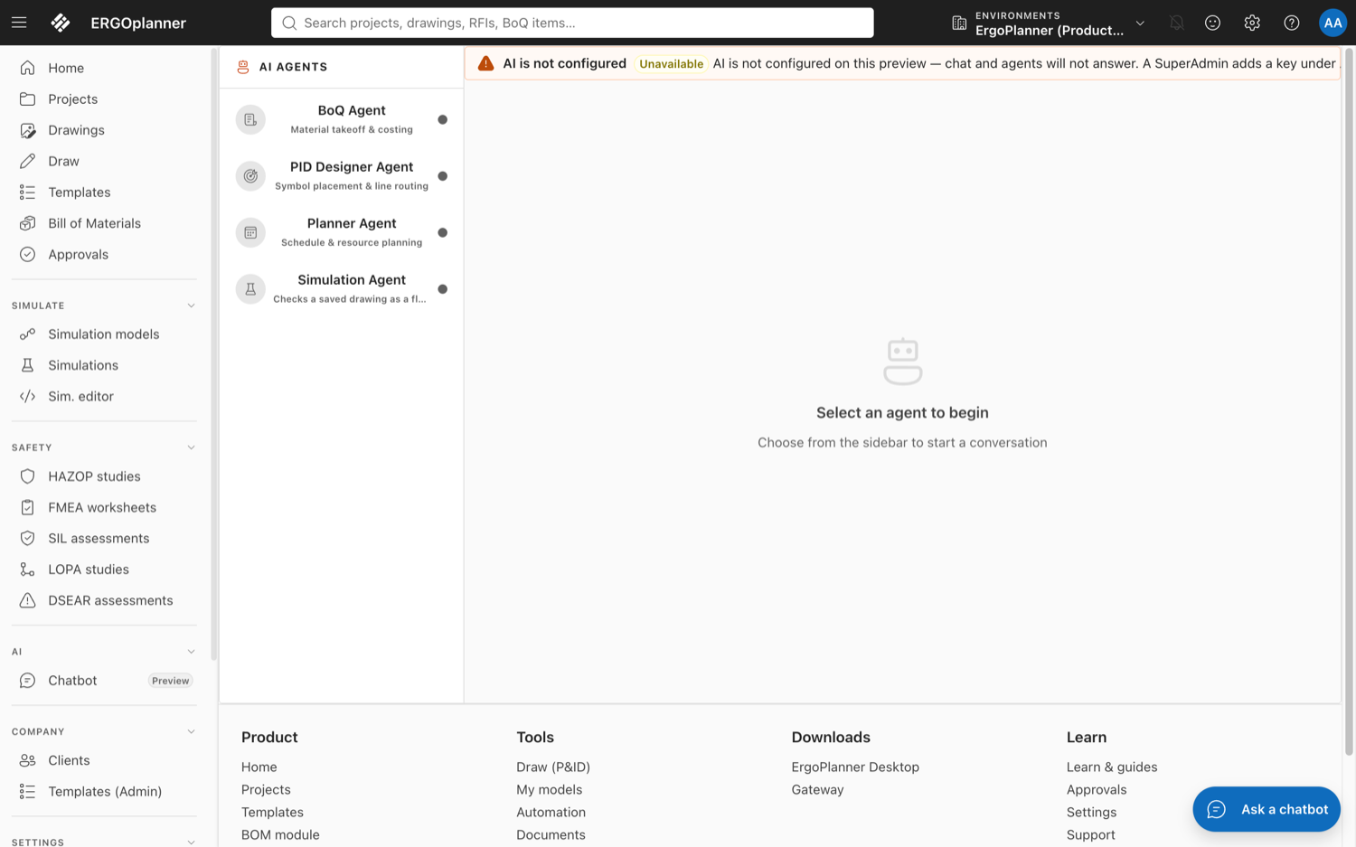
Those four are the whole set. Any other agent name you may see in an older document or a saved agent workflow has no implementation behind it and will not answer.
Two other places show agent work against this project:
- Agent Dashboard (
/admin/agent-dashboard) — pick your project and read Overview, Health, Sessions, History, Metrics and Settings tabs for it. - Agent workflows (
/admin/agent-workflows) — chain agents into a sequence.
The validation pass
Separately from the agents, the Validation button in the Draw toolbar runs the drawing's own checks — an instant client-side check as you draw, plus a deeper server check on save, merged into one list. The button badges the issue count and turns red while there is at least one issue. Clear the errors here before you generate the BoM; see Server-Side Validation.
Part 6 — Generate and export the Bill of Materials
The BoM is derived from the drawing. You do not assemble it by hand.
- A BoM is created with the drawing and re-synced on every save, manual or autosave. A "BOM updated" notification appears in the canvas header when a sync finishes.
- To open it from the editor: expand the ribbon (Expand Ribbon), find the Import / Export group, and click Bill of Materials (BoQ, Line List).
- To open it from the sidebar: Bill of Materials (
/admin/bom), then click your BoM's row.
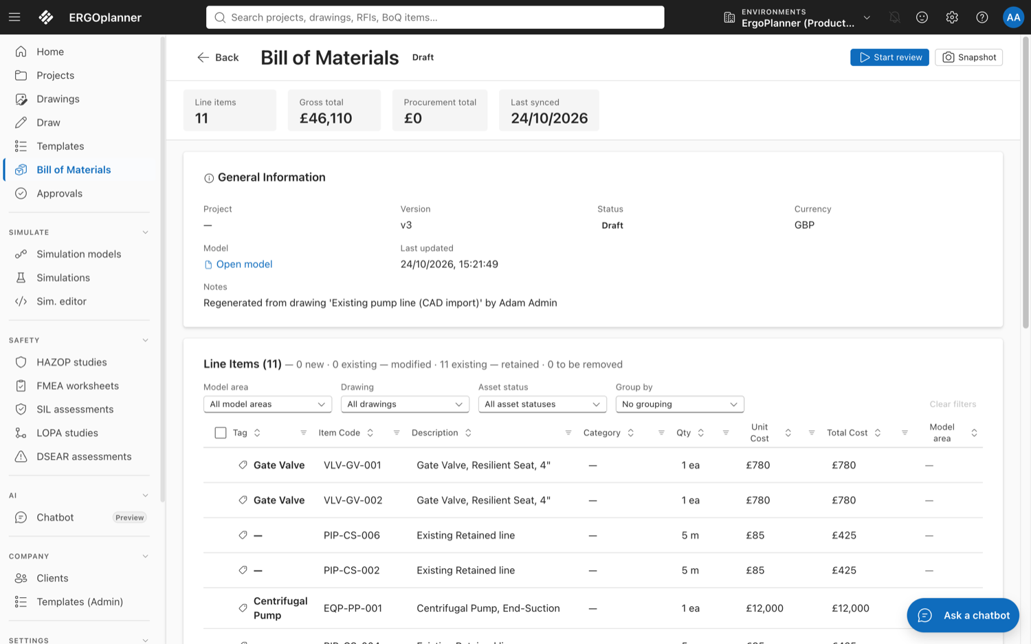
The detail view gives you one row per placed symbol — item code, description, quantity, unit, unit cost, line total — each linked back to the symbol it came from, with filters by area or sheet and a running total for the current filter.
- If you need a refresh outside the save cycle (after a bulk template operation, say), use Generate BOM in the BoM list's command bar, pick the drawing, and click Generate.
- To export: Export CSV in the BoM list's command bar downloads every BoM currently visible under your filters as
bom-export.csv.
Quantity overrides, the override-approval path and the BoM statuses (Draft / Approved / Rejected) are covered in Bill of Materials.
Where to go next
Your drawing exists and its BoM balances. The next thing a real project does is issue it:
- Issuing a Drawing — freeze a revision, assemble the register, send a transmittal
- Running a Design Review — comments, the five-state comment lifecycle, and who can move a comment to which state
- A Revision Cycle — Rev A → Rev B, comparing two revisions, and the project stage gate
See also
- Drawing Templates Overview — authoring your own templates
- Drawing and Connecting — manual drawing on the same canvas
- Project Schedules — what the Planner agent works on