Appearance
Quick Start Guide
Create your first wastewater treatment simulation in 10 minutes
Overview
This guide walks you through creating a simple activated sludge plant simulation from scratch. By the end, you'll understand the core workflow of ErgoPlanner.
Prefer to start from something already built? See Load the sample project below.
Load the sample project
A brand-new workspace is empty. Rather than draw a plant before you have seen one, you can have ErgoPlanner build a complete worked example in your own workspace, in a couple of seconds.
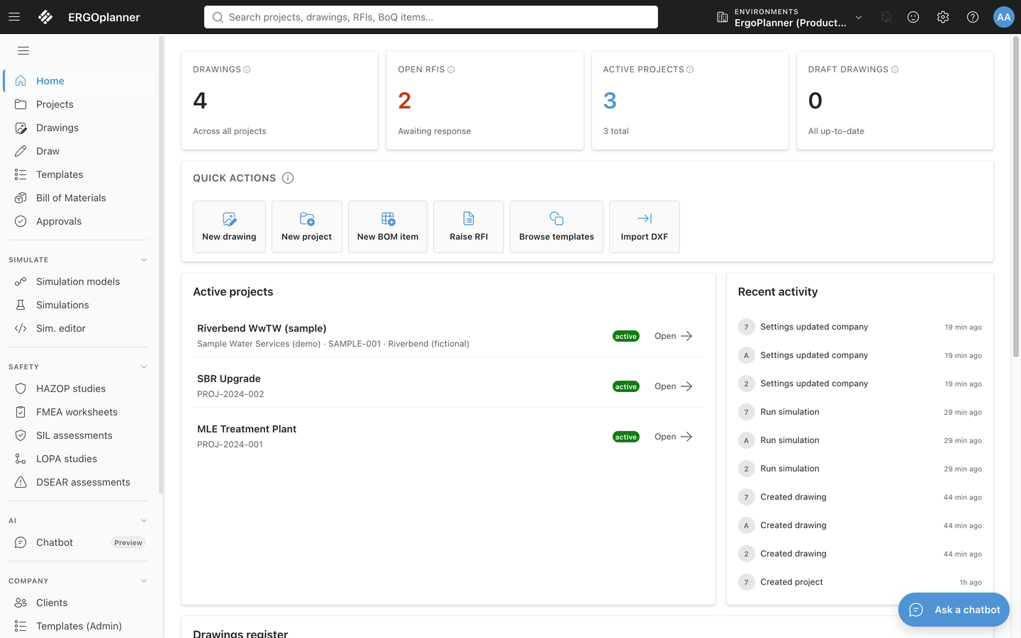
Signing in lands you on Home, which is where most journeys start: counters for drawings, open RFIs, active projects and draft drawings; a Quick actions row; your active projects; recent activity; and the drawings register below.
The Quick actions row: New drawing (name and project, then a blank canvas), New project, New BOM item (opens the Bill of Materials), Raise RFI (opens RFIs with the New Request for Information dialog already open; Create RFI adds it to the register), Browse templates, and Import drawing (name and project, then the new drawing opens in Draw with the Import CAD Drawing dialog, which takes a DWG, DXF or a vector PDF exported from CAD), and Turn a P&ID into a live model (drop a P&ID image or PDF, choose its pages if the PDF has several, choose a project; the new drawing opens in Draw ready to recognise, see Importing a P&ID). A demo workspace shows only the tiles for the features it was given, and never Raise RFI (RFIs are not part of a demo). The drawings register's Import JSON button restores a drawing exported as JSON; it does not read CAD files.
Where to find it
- On the Projects page, the empty state shows a Try a sample project card — click Open sample project.
- If you already have projects, the same action lives under New project ▾ → Load sample project in the command bar.
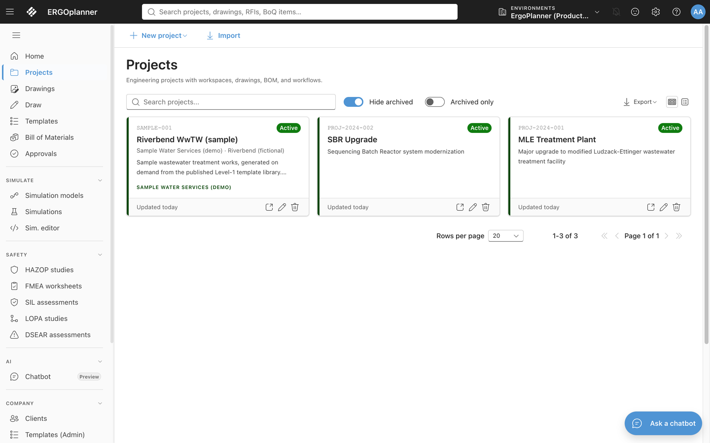
What you get — one project, Riverbend WwTW (sample), containing:
| Artefact | What it holds |
|---|---|
Drawing P&ID-001 | Three sheets — P-101 primary settlement, P-102 biological treatment, P-103 intermediate pumping station — with tagged equipment, instruments and pipelines, built from the published Level‑1 template library |
| P&ID model | The same plant as a Level‑2 model, which is what the two views below look at |
| Two views | Primary settlement area and Activated sludge lane — two lenses on the one model, not two drawings. See Views and the review |
| Bill of Materials | Generated from the drawing, with line items for the valves, pumps, tanks and instruments on it |
| HAZOP study | A skeleton with one node per sheet, ready for your study team. No deviations are pre-filled — those are the team's judgement, not the software's |
| Outline programme | A short schedule covering process design, P&ID development, HAZOP and BoQ, ending at a design-freeze milestone |
| Simulation model | Compiled from the drawing's process areas, so you can open it in the simulation editor and run it |
Views and the review
A view is a lens on the model: a named slice of the same elements, issued and revised on its own. The sample ships two, cut over different parts of the same P&ID model, and deliberately leaves them in different states.
| View | Status | Frozen? |
|---|---|---|
| Primary settlement area | S3 — shared for review & comment | Yes, Rev B |
| Activated sludge lane | S0 — work in progress | No |
Freezing takes an immutable snapshot of what a view contains and records it as a revision. That revision is what a review comment attaches to, which is why:
- You can comment on Primary settlement area straight away — open it and leave the first one.
- Commenting on Activated sludge lane is refused, with "This view has no revision yet… freeze the view first, then comment on it." That is not a fault; it is what freezing is for. Freeze it and the same comment goes through.
The sample's third process area — the intermediate pumping station — has no view at all. A view is a lens somebody chose to cut, not a mirror of the sheet list.
No comments are pre-filled. The first comment on the frozen view is yours to leave.
On approval status. Neither view is marked approved (S4, A or AB), because nobody has approved them. The Stage 3 release gate checks exactly that, so the sample starts where a real project starts: issued, awaiting review. Walk a view through review and advance its status, and the gate's answer changes because the design did — not because the sample pretended.
Notes
- It is yours to change. Rename it, edit the drawing, delete it — nothing about it is special to the software. The plant is fictional.
- One per workspace. Clicking again opens the sample you already have rather than making a second one, and the action disappears once it exists.
- Permissions. You need permission to create projects (Owner, Admin or Project Manager). The action is hidden for roles that cannot.
- It counts towards your plan's project allowance like any other project.
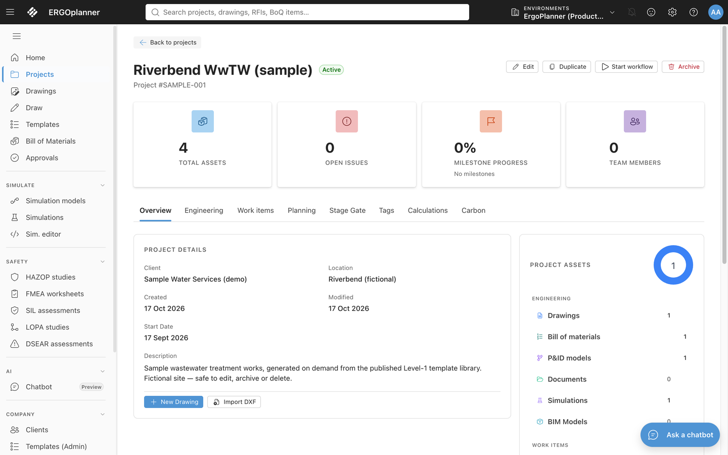
Open the drawing from the project page and continue with Step 2 to find your way around the canvas — or follow the steps below to build a plant from scratch.
Step 1: Create a New Project
- Click New Project from the dashboard
- Enter project details:
- Name: "My First Plant"
- Description: "Tutorial plant - activated sludge"
- Client: (Optional)
- Click Create
Step 2: Open the Drawing Canvas
The drawing canvas is where you build your process flow diagram:
- Left Panel: Stencil library with process units
- Center: Drawing canvas
- Right Panel: Properties panel for selected items
- Bottom: Results and simulation controls
Step 3: Add Process Units
Add an Influent Source
- Expand Auxiliary Equipment in the stencil panel
- Drag Influent onto the canvas
- Click the influent to select it
- In the Properties panel, set:
- Flow: 10,000 m³/d
- COD: 500 mg/L
- TSS: 250 mg/L
- TKN: 45 mg/L
- TP: 8 mg/L
Add a Primary Clarifier
- Expand Primary Treatment
- Drag Primary Clarifier onto the canvas
- Set properties:
- Surface Area: 500 m²
- Depth: 3.5 m
- Calculation Mode: Basic
Add an Activated Sludge Reactor
- Expand Biological Treatment
- Drag CSTR Reactor onto the canvas
- Configure:
- Volume: 5,000 m³
- MLSS: 3,500 mg/L
- DO Setpoint: 2.0 mg/L
- Biokinetic Model: ASM1
Add a Secondary Clarifier
- Expand Secondary Treatment
- Drag Secondary Clarifier onto the canvas
- Set:
- Surface Area: 800 m²
- Depth: 4.0 m
- RAS Rate: 100%
Add an Effluent
- Expand Auxiliary Equipment
- Drag Effluent onto the canvas
Step 4: Connect the Units
- Click on the Influent unit
- Find the output port (right side)
- Click and drag to the Primary Clarifier input port
- Continue connecting:
- Primary Clarifier → CSTR Reactor
- CSTR Reactor → Secondary Clarifier
- Secondary Clarifier → Effluent
- Secondary Clarifier (RAS) → CSTR Reactor (return)
Your flow diagram should look like:
Influent → Primary → Reactor → Secondary → Effluent
                        ↑          |
                        └── RAS ───┘
Step 5: Run the Simulation
- Click the Run Simulation button (play icon)
- Select Steady-State mode
- Click Start
The simulation will:
- Calculate mass balances through each unit
- Converge to steady-state conditions
- Display results on each connection
Step 6: View Results
Stream Results
Click on any connection to see:
- Flow rate (m³/d)
- COD concentration (mg/L)
- TSS concentration (mg/L)
- Nitrogen species (NH4, NO3)
- Phosphorus
Mass Balance Table
Open View > Mass Balance to see:
- COD removal efficiency
- Nitrogen removal (if configured)
- Phosphorus removal
- Sludge production
Unit Performance
Click on any unit to see:
- Operating parameters
- Removal efficiencies
- Energy consumption
- Design margins
Step 7: Save Your Project
- Click File > Save (or Ctrl+S)
- Your project is saved automatically to the cloud
- Access it anytime from the dashboard
What's Next?
Now that you've created your first simulation:
- Add More Units: Try adding sludge treatment
- Configure Controllers: Add DO control to the reactor
- Run Dynamic Simulation: See how the plant responds to load changes
- Explore Templates: Use pre-built plant configurations
Recommended Next Steps
| I want to... | Go to... |
|---|---|
| Learn the interface | Interface Overview |
| Learn keyboard shortcuts | Keyboard Shortcuts |
| Understand process units | Process Units Overview |
| Add process control | Controllers Overview |
| Try a template plant | Templates |
Common Questions
Why isn't my simulation converging?
- Check that all units are properly connected
- Verify influent parameters are realistic
- Ensure biological parameters are within normal ranges
How do I add nutrients?
Add a Chemical Dosing unit and connect it to your reactor:
- Drag Nutrient Addition from Chemical Dosing
- Connect to reactor input
- Configure N and P addition rates
How do I see COD removal?
Open the Mass Balance table:
- View > Mass Balance
- Look at the COD row
- Compare Influent vs Effluent columns
Video Tutorial
Watch the Quick Start Video Tutorial for a visual walkthrough.