Appearance
Importing a P&ID
The headline workflow: import a scanned P&ID image and let AI symbol recognition turn it into native, editable drawing elements.
What the import does
You give ErgoPlanner a PNG or JPEG image of a P&ID — a scan, a photo, or an export from another CAD tool. The image is placed on the sheet as a background image, and the AI recognition pipeline detects the symbols on it and places matching, fully editable stencil symbols on top. From there you review, correct and complete the drawing with the normal editing tools.
A worked example: a scanned P&ID of a sewage pumping station becomes a native drawing with pumps, valves and instruments you can move, retag and connect.
Starting the import
Import Drawing is available in three places — all run the same flow:
- The Import Drawing button in the toolbar (after the Line Type dropdown).
- File → Import Drawing... in the menu bar.
- The Import Drawing button on the "No drawing open" screen.
Steps:
- Click Import Drawing and pick a PNG or JPEG file.
- If no drawing is open, the Create new drawing dialog appears first — name the drawing and pick a project (Creating a Drawing). Cancelling the dialog cancels the import.
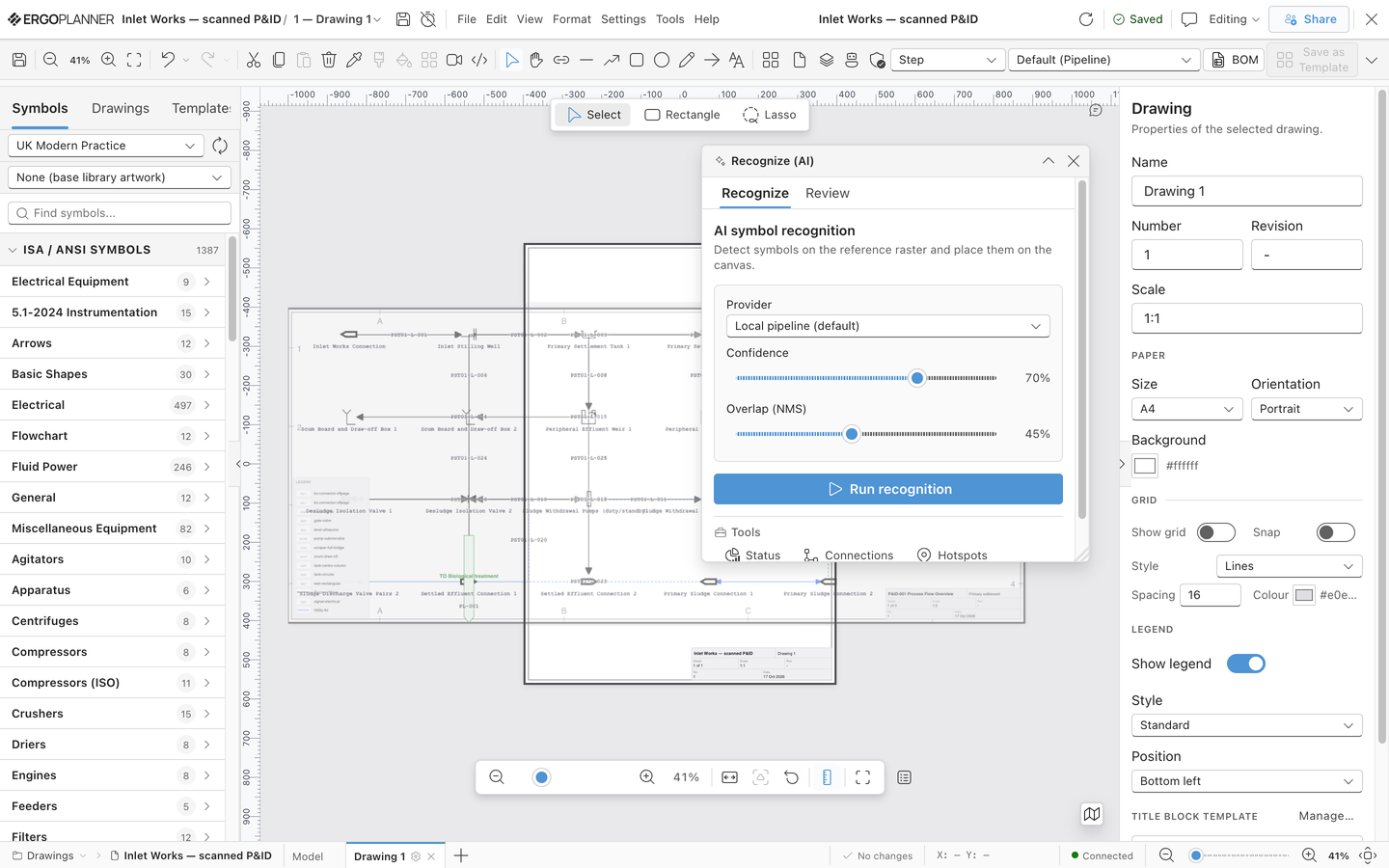
- The image is placed centred on the sheet as a Background Image layer (Background Images), and the editor enters recognition mode with the Recognize (AI) panel open.
Starting from Home: Turn a P&ID into a live model
The Turn a P&ID into a live model quick action on Home takes a P&ID image or PDF straight into a new drawing:
- Click Turn a P&ID into a live model. A dialog opens; drop the file on it, or click it (or press Enter) to browse.
- A PDF with more than one page opens Choose the pages to recognise as soon as the upload finishes (see below). A single-page PDF or an image skips this step.
- Choose a project for the P&ID asks for the drawing name (the file name, which you can change) and the project. Create and recognise creates the drawing.
- Draw opens the new drawing with the P&ID on the sheet and the Recognize (AI) panel up, on the pages you chose. Press Run recognition.
Cancelling at the project step discards the upload. If you reload the page before the drawing opens, the upload is lost and Draw says so; start again from Home.
The file is uploaded once: Run recognition in Draw works on that same upload instead of sending the file again.
Choosing the pages of a multi-page PDF
When the PDF has more than one page, the Choose the pages to recognise dialog opens before recognition starts:
- Every page is ticked by default, each with a small thumbnail (documents of more than 24 pages show page numbers only).
- Select all and Clear change the whole selection; the counter reads, for example, "2 of 3 pages".
- Start recognition is disabled while no page is ticked. Only the ticked pages are recognised; each proposal remembers the page it came from.
- If the server rejects the selection (a page outside the document, or a repeated page) the message appears under the page list and nothing is recognised.
A single-page PDF, or any image file, skips the dialog and recognises as before. Run recognition then sends only the ticked pages.
The Recognize (AI) panel
The floating Recognize (AI) panel has two tabs — Recognize and Review. The Recognize tab is the starting point; the Review tab carries a badge with the outstanding count and holds everything that happens after a run, including the per-hotspot Identify view (see Reviewing Recognition Results and Identifying Hotspots).
Controls on the Recognize tab
| Control | What it does |
|---|---|
| Provider | The recognition engine. Leave on Local pipeline (default) — it runs the built-in detector. (Claude CLI (dev) is a development/validation path.) |
| Confidence | How sure the detector must be before it reports a symbol (default 70%). Lower it to find more symbols at the cost of more false positives; raise it for fewer, cleaner detections. |
| Overlap (NMS) | How much two detections may overlap before the weaker one is discarded (default 45%). Usually fine at the default; raise it only if legitimately overlapping symbols are being merged. |
Running recognition
Click Run recognition. If the button is disabled, the panel tells you why — the drawing engine is still loading, a collaboration sync is in progress, or there is no reference raster on the canvas yet.
While running, the panel shows "Recognizing symbols…". Then:
- Success — a green box reads "Recognition complete" with counts of symbols placed and connections, and offers:
- Review & place hotspots — jumps to the Review tab, the grid of everything recognition found, with per-row and place-all actions.
- Save as Template — captures the recognised symbols and connections as a reusable drawing template (see Drawing Templates).
- Nothing found — the panel suggests lowering the Confidence threshold or using a higher-resolution image, then running again.
- Error — the failure message is shown with a Retry button.
Re-running
Runs are additive: a re-run adds to what is on the canvas. Use Clear previous run (shown once a run exists) to remove exactly the previous run's placed symbols and connections — elements you drew yourself are never touched. Typical loop: run, inspect, clear, adjust Confidence, run again.
The Tools chips
Below the Run button, the Tools row opens companion panels on demand:
| Chip | Panel |
|---|---|
| Status | Recognition status/statistics panel |
| Connections | Detected pipeline connections |
| Hotspots | The list of detected hotspots (regions of interest) |
| OCR Tags | Text/tag recognition results |
| Calibrate | Align the recognition frame to the raster's true scale and aspect ratio |
After the run
- Open the Review tab and work through the grid — accept, fix or reject each detection, then place them: Reviewing Recognition Results.
- For regions the detector could not classify (or missed entirely), use the Identify view and the manual hotspot tools: Identifying Hotspots.
- Adjust or hide the underlying raster as you trace over it: Background Images.