Appearance
Importing a CAD Drawing (DXF, DWG or a PDF from CAD)
Bring an existing AutoCAD drawing onto the sheet as editable symbols and connections. DXF is parsed in the browser; DWG is read natively on the server — nothing has to be converted to DXF first. A PDF exported from CAD is read as vector linework and text, and its tag text suggests the symbols.
This is the deterministic brownfield route: the blocks in your CAD file are matched to library symbols by a mapping table you choose, and the matches are placed. It does not look at pixels and it does not guess — contrast with Importing a P&ID, which works on a scanned image.
Where it is
In the Draw toolbar, the upload button (tooltip Import CAD Drawing) opens the Import CAD Drawing dialog.
- The drop zone reads "Drop a DXF, DWG or PDF file here" with an .DXF · .DWG · PDF (vector, from CAD) badge; click it to browse.
- Any other file type is rejected inline with "Please select a DXF, DWG or PDF file".
- A drawing must already be open, because the import is placed onto the open drawing. The dialog itself does not create one for you.
- From Home: the Import drawing quick action asks for a drawing name (default Imported drawing and today's date) and a project (pick one, or Create a project), then Create and import makes the drawing in that project and opens it in Draw with this dialog already open.
- A project's own page has an Import DXF button that opens Draw on this dialog for that project.
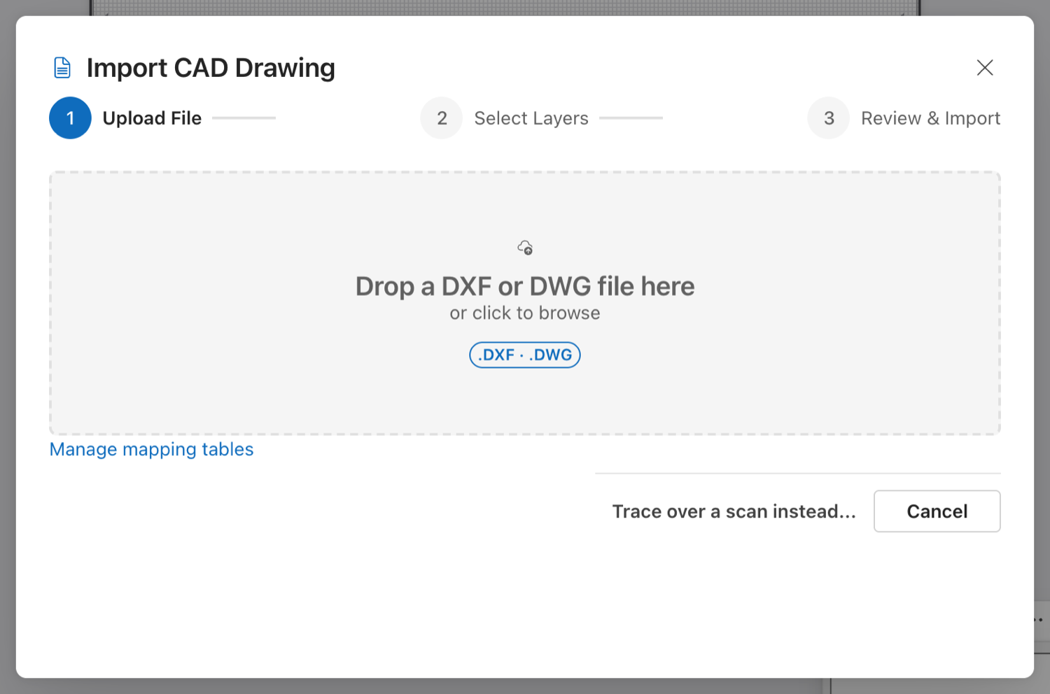
The dialog now also accepts a vector PDF exported from CAD (badge ".DXF · .DWG · PDF (vector, from CAD)"); the screenshot predates that.
Two routes, picked by file extension
| File | Parsed by | Dialog steps |
|---|---|---|
| .dxf | The browser | Upload File → Select Layers → Review & Import |
| .dwg | The server (ACadSharp) | Upload File → Map Blocks → Review & Import |
| .pdf (exported from CAD) | The browser (vector paths and text) | Upload File → Scale & Suggest → Review & Import |
You do not choose the route — picking the file does. The stepper relabels itself, and the DWG path skips layer selection entirely because layer handling happens inside the server pipeline.
DWG needs the WebGPU drawing editor, because the server pipeline places its result straight into the live engine. On the older editor the dialog refuses with:
DWG import needs the WebGPU drawing editor. Save the drawing as DXF, or switch editors.
On the DXF (browser) path the layer-selection step decides which process layers are searched for symbols and pipes. Sheet layers (layer 0, TITLE, BORDER, FRAME, SHEET, VIEWPORT, ANNOTATION) start unticked there, but they still come across as sheet background when Keep sheet background is on (see below). Unticking any other layer leaves it out completely.
A PDF exported from CAD (vector import)
Use this when all you have is a PDF that was plotted from CAD, not scanned. Such a PDF still holds the drawing as lines and text, and the import reads them directly: nothing is rasterised.
On the Scale & Suggest step the dialog says what the page holds, for example "Page 1 of 1: 420 × 297 mm paper, 14 vector path(s), 12 text run(s)". For a multi-page PDF, pick the Page to import. Then set Scale to mm:
- Paper size (1:1, 1 pt = 0.353 mm) places the sheet at its paper size, so an A3 PDF lands as a 420 × 297 mm sheet. This is the default.
- Drawing scale 1:N multiplies the paper size by N. Use it when the drawing was plotted to a scale, for example 50 for 1:50.
- Two known points works like the reference overlay's calibration: click two points on the page preview whose real distance you know, then type that distance in millimetres.
The line under the options gives the resulting scale and the size the page lands at. Import stays disabled until the scale is complete.
What comes across:
- Linework: every stroked path (lines, polylines, rectangles and curves, which are flattened to short segments) keeps its colour and line weight. Filled shapes come across as outlines. A white fill, or a fill covering the whole page, is the paper and is left out.
- Text keeps its position, height and rotation.
- The title block: labelled text such as
TITLE,DWG NO,REVandDATE(with the value beside or below the label, or after a colon) fills the sheet's title-block fields when Fill the drawing's title-block fields is ticked.
All of it lands on the same locked CAD background layer as a DXF or DWG sheet (see below), so it is never in the Bill of Materials.
Suggest symbols from tag text (ticked by default) looks for tag-like text: one to four letters, a hyphen and two to five digits, with an optional letter, such as P-101, V-201, FT-301 or FIC-101A. Line numbers (100-P-001), sizes (DN100, PN-16) and standards (ISO-9001) do not count. Each distinct tag becomes an unmapped-block placeholder at the tag's position, carrying the tag. The placeholders are grouped by tag prefix (P-* pump, FT-* flow transmitter), so the Resolve CAD blocks panel maps every pump in one choice and suggests a matching symbol from the prefix. A text run that is only the tag is replaced by its placeholder. Longer text, such as P-101 FEED PUMP, also stays on the background.
A scanned PDF has no vector drawing, only an image of one. The dialog detects this and says so: "This PDF has no vector drawing: it is a scan or an image." Open as reference overlay closes the import and opens the reference overlay with the same file already loaded, ready for its two-point scale (Background Images).
A PDF has no blocks and no pipe topology, so nothing is placed as a connected symbol. The tag placeholders are the starting point, and you draw the pipes over the background. Like the DWG route, the PDF route needs the WebGPU drawing editor:
PDF import needs the WebGPU drawing editor.
The DWG path, step by step
Step 2 — Map Blocks
While the file uploads and the server reads it, the step shows a progress bar and "Uploading and reading the drawing on the server…".
When it is ready you get two count cards — Blocks found and Layers — and two controls:
| Control | Notes |
|---|---|
| Treat imported equipment as | Existing — retained (default), Existing — modified or New. Stamped as the asset status on every symbol the import places, which is what the Bill of Materials reads. With Existing — retained, imported pipe runs that have no specific line type get the Existing Retained line type too. The DXF route has the same choice among its Options. |
| Block mapping table | Hint: "Maps the drawing's CAD blocks to library symbols. Preselected from the drawing's block names." A searchable dropdown, because the list grows once a company has several CAD libraries. |
Option labels carry the auto-detect score for this drawing, e.g. Plant 3D Default — 86% match (recommended). That percentage is the detector's figure for your block names against that one table — it is not a product accuracy number.
How the preselection is worked out. The server scores every mapping table it holds against the block names found in your drawing: exact symbol matches count 1, probable pipe matches count ½, divided by the total number of blocks. A table scoring above 0.7 is marked recommended. The dialog preselects the recommended table; failing that, the highest non-zero score; failing that, Plant 3D Default.
Three mapping tables are built in — Plant 3D Default, BS 1553 Default and Bentley OpenPlant Default — and any tables your company has added are scored alongside them. Tables are managed under Settings → CAD import mappings in the sidebar (the dialog links to it as Manage mapping tables).
No screenshot: this step belongs to the DWG route, which the capture environment could not run. The DXF route's equivalent, the Block Mappings tab, is shown in the next figure.
Press Import to run. The button is disabled until the step has finished preparing; while running it reads Importing... and the step shows "Mapping blocks, tracing pipes and placing symbols…".
Back is disabled while the dialog is preparing or importing. Going back from the DWG path resets the import — you choose the file again.
Step 3 — Review & Import
A success bar states what landed: "Placed N symbols and M connections on the drawing." Below it, three counts from the pipeline: Blocks mapped, Blocks unmapped, Connections traced.
Then, when they apply:
| Message | Means |
|---|---|
| A line saying how many blocks were kept as placeholders, with a Resolve CAD blocks… button | Blocks no mapping rule matched are not dropped; see below. |
| "N low-confidence symbol(s) were not placed. Check the drawing against the source." | The mapping matched those blocks, but below the pipeline's confidence bar (0.8). They were recorded against the import session and not put on the canvas. |
| "N pipe run(s) could not be connected to a symbol." | A traced line had no symbol at an end. |
| "The drawing was read, but no symbols could be placed with this mapping table." | Nothing cleared the bar. Try a different mapping table. |
| Plain notes at the bottom | Non-fatal warnings from the pipeline, listed verbatim. |
Errors appear as a red bar at the top of the dialog, above the stepper. A failed import ends with "…Go back and choose the file again to retry." — that is literal advice, not boilerplate: see the limits below.
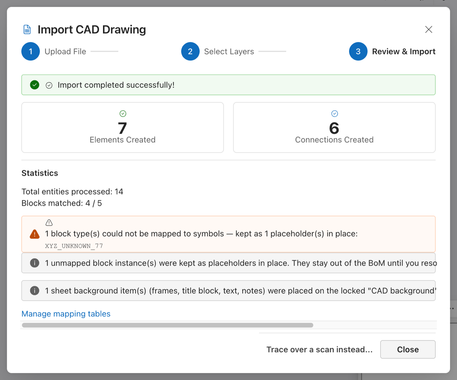
Unmapped blocks are kept as placeholders
On both routes, a block the mapping could not match stays on the drawing as a placeholder: a dashed box labelled with the block name, at the block's exact position and rotation, carrying the block's name and attributes. A placeholder is not counted in the Bill of Materials until you resolve it.
Closing the dialog after an import that left placeholders (or Tools → Resolve CAD blocks… at any time) opens the Resolve CAD blocks panel. It lists each block name once with its instance count, a suggested library symbol, a searchable symbol picker (plus Keep as placeholder and Ignore (delete instances)) and a Show button that selects and frames the instances. Apply replaces every instance in place (same position, rotation, layer, tag, CAD attributes and asset status; connected pipes are re-attached) as one undo step. With Remember for future imports ticked, each choice is written as an exact-name rule into your company's <company> CAD mappings table, so the next import of that CAD library maps those blocks automatically. The full walk-through is in Brownfield: Starting From CAD Drawings You Already Have.
The rest of the sheet: frame, title block, text and notes
Both routes keep the rest of the sheet, so an imported drawing looks like the original and can become a template. The options sit under Sheet background in the dialog (the DXF options and the DWG Map Blocks step), all ticked by default:
- Keep sheet background brings across the drawing frame and other loose linework (lines, polylines, arcs, circles), hatch outlines, dimension text, and every TEXT and MTEXT note that did not become an equipment tag or a pipe's line tag. Each item keeps its CAD layer name, colour, line weight, and text height and rotation. ByLayer and ByBlock colours are resolved. White (colour 7) is drawn in the theme's dark neutral so it shows on white paper.
- Keep the title block keeps the title block's lines, labels and attribute values with the sheet. Untick it to leave the title block's geometry out.
- Fill the drawing's title-block fields copies the title block's drawing number, title, revision and date into the open sheet's own title block. The fields are read from the
DWG_NO/DRG_NO/NUMBER,TITLE(orTITLE1,TITLE2and so on),REV/REVISIONandDATEattributes, and case does not matter. The sheet's revision letter is set too. This works even when the title block's geometry is left out.
The title block is found by its block name: one containing TITLE, BORDER or FRAME, or a TB name such as TB_A1. If no name matches, the import takes the attributed block in the lower-right corner of the drawing frame. The title block is never turned into an unmapped-block placeholder.
The sheet background is placed as ordinary drawn shapes and text on its own layer, CAD background. The import creates that layer, and it is locked, so you cannot select, move or erase its contents by accident. Unlock it in the Layers panel (View → Show Layers Panel) to edit the sheet, or hide it to see only the engineering content. The background is not made of symbols, so it never appears in the Bill of Materials and is never reserved as a tag, even when a note reads like one. The Review step says how many background items were placed and which title-block fields were filled.
A very large sheet keeps at most 20,000 background entities, and a note in the Review step says how many were left out. The server route keeps the frame and title layers first. Untick Keep sheet background to import only the engineering content.
The sheet background needs the WebGPU drawing editor. On the older editor the option is unavailable and a DXF import brings across symbols and pipes only.
Import as template
The last step of the dialog has an Import as template button (and Tools → Import as template… opens this dialog for it). It continues from the import into Resolve CAD blocks, checks that no placeholder is left, then opens the Save-as-Template wizard with the name prefilled from the title block. The sheet background goes into the template as decoration. See Drawing Templates: Import as template.
What happens to the drawing
The whole import is one write to the drawing engine. Everything the server needs to say is read first, so a network failure never leaves half an import on the canvas. Once placed, the symbols and connections are ordinary editable elements — move, retag and reconnect them like anything you drew.
The drawing is marked changed, so the normal save/autosave behaviour applies (Creating a Drawing).
What this does not do
- It does not convert DWG to DXF. The server reads the DWG itself. There is no converter step and no intermediate file for you to manage.
- It does not place low-confidence matches. Only blocks mapped at 0.8 confidence or better go onto the canvas. The rest are counted in the Review step and left behind — there is no review grid for them on this path, so if the count is high, change the mapping table rather than hunting for them.
- The import itself does not learn. Auto-detect only scores mapping tables that already exist. A table changes only when you edit it, or when you resolve blocks in the Resolve CAD blocks panel with Remember for future imports ticked.
- It is one import per file selection. The pipeline stages its results against the upload session, and running it twice on the same session would duplicate them, so the Import button runs once. To retry, go Back and pick the file again.
- Custom mapping tables are saved per company. They are stored in the database, survive restarts and are never visible to other companies. The three built-in tables are shared and read-only (duplicate one to change it). Use Export as JSON to share a table outside your company.
- It does not recognise anything from an image. No symbol detection, no OCR, no confidence tuning. If you have a scan rather than a CAD file, that is a different workflow — see Importing a P&ID.
- It does not size the paper or set a scale for you. The result is fitted to the drawing's own extents so proportions are right. The CAD frame and title block come across as locked background, but the sheet's paper size, scale and Draw title-block template remain yours to set.
Limits worth knowing
- Uploads are capped (50 MB by default for the import service). A larger DWG is rejected at upload.
- The import is filed under the project in the Draw URL (
?projectId=…). Open the drawing from the drawings register or a project page so that the import session belongs somewhere; opened without one, the session is simply unfiled. - Only blocks are mapped. Loose geometry, text and dimensions are kept as sheet background (above), not turned into symbols. Hatch fills are drawn as outlines only. A dimension keeps only its text on the DXF path, and only when the text is overridden in CAD.
No CAD source?
A PDF plotted from CAD imports as vector (above). To trace over a scan or a scanned PDF instead, use Trace over a scan instead… in this dialog, or Insert → Reference image…. See Background Images.
See also
- Importing a P&ID — the image/recognition workflow, which is a different thing
- Drawing and Connecting — editing what the import placed
- Client Standards — symbol libraries the mapping tables point at