Appearance
Tutorial: Brownfield — Starting From CAD Drawings You Already Have
You have DXF or DWG files (or PDFs plotted from them) from your existing CAD system. Bring them in, map their blocks to your symbol library, separate what already exists from what you are adding, and end at the Bill of Materials.
Time required: 45–60 minutes Difficulty: Intermediate Prerequisites: A DXF or DWG file of a P&ID (or a PDF exported from CAD), and an account with the Engineer role or higher
What you will have at the end
- A project and a drawing holding your existing plant as native, editable elements
- A block-mapping table for your CAD library that learns every block you resolve, so the next import of the same library maps it automatically
- New work placed alongside the existing plant, visually and structurally distinguishable
- A Bill of Materials over the whole drawing
This tutorial is about CAD import, which is deterministic. Blocks are matched to symbols by name, through mapping rules you can read and edit. It is not about scans: ErgoPlanner's recognition of raster P&ID images is a separate, gated capability with known accuracy limits — see Importing a P&ID for what it does and does not do. If you have a CAD source, use it. Import the CAD.
Part 1 — Project and drawing
Same first two steps as the greenfield route, so they are not repeated here:
- Projects → New project — fill Project name and Project number (unique), optionally Client, Location and Description, then Create project. Full field table in A Greenfield Project.
- Draw → Create new drawing — name it, pick the project, and fill in the optional Drawing information (drawing number, revision, status). See Creating a Drawing.
Turn autosave on before importing.
Part 2 — Choose your mapping table first (optional, but do it once)
A mapping table is the rule set that turns your CAD library's block names into ErgoPlanner symbols. Three tables ship built in — Plant 3D Default (AutoCAD Plant 3D), BS 1553 Default and Bentley OpenPlant Default — and the import falls back to the Plant 3D one. If your blocks are named in your own house convention, none of the three will cover them, and writing your own table is the work that makes the import land.
Go to Settings → CAD import mappings on the sidebar (/settings/import-mappings) — the Import Mappings page. The CAD import dialog and the Resolve CAD blocks panel (Part 3c) also carry a Manage mapping tables link to it.
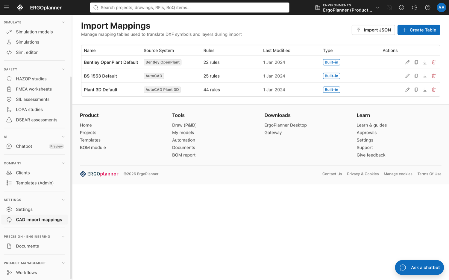
Its subtitle says what it is for: "Manage mapping tables used to translate DXF symbols and layers during import." The page lists every table with its Name, Source System, rule counts, Last Modified and Type, and carries two buttons — Import JSON and Create Table. Per-table actions are View / Edit rules, Duplicate, Export as JSON and Delete — built-in tables can be viewed and duplicated but not deleted.
To make your own:
- The quickest start is to Duplicate the built-in table and edit the copy. Otherwise click Create Table and fill Name (e.g. Standard DXF Mappings) and Source System (e.g. AutoCAD, Visio, Bentley).
- Open the table's rules. The editor has two tabs:
| Tab | What a rule says |
|---|---|
| Symbol Rules | Maps block names to symbol keys using glob patterns. Columns: Pattern, Symbol Key, Category, Label, Priority. |
| Layer Rules | Maps layer names to pipe line types. Columns: Pattern, Pipe Line Type, Priority. |
- Patterns are globs:
*matches any run of characters,?matches one,**matches across path separators. So a symbol rule ofPUMP_*→pump.centrifugalcatchesPUMP_01,PUMP_SUMP_Aand the rest. Priority decides which rule wins when two patterns both match. - Use Export as JSON to hand the table to a colleague, and Import JSON to load one you were given — the confirmation dialog shows its name, source system and its symbol- and layer-rule counts before you accept it.
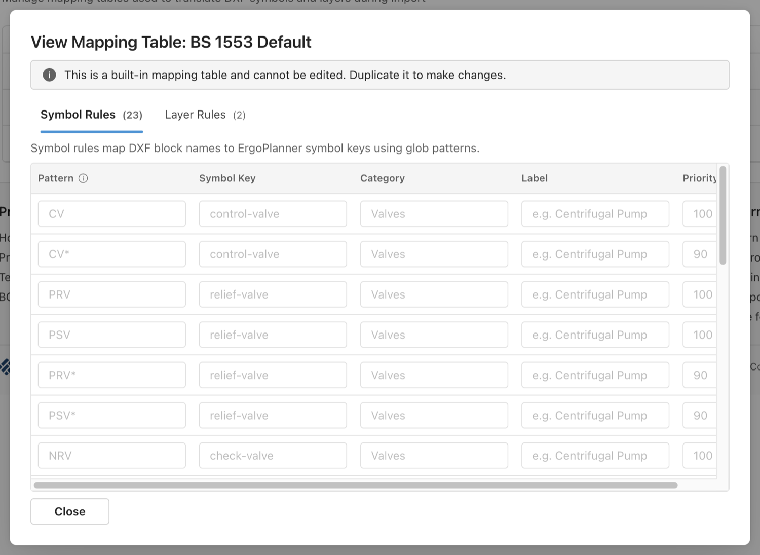
What a saved table buys you, exactly. On the next import, auto-detect (Part 3) scores the tables you already have against the block names in the file you just uploaded, and preselects the best-scoring one. An import on its own does not change a table — but resolving the blocks it could not map does: when you resolve them in the Resolve CAD blocks panel with Remember for future imports ticked (Part 3c), each choice becomes a rule in your company's table. You do not have to write rules up front; you can import first and teach the table as you go.
Custom tables are stored per company. A table you create, duplicate, import or that the resolve panel creates is saved in the database for your company: it survives restarts and other companies never see it. The three built-ins are defined by the product, shared and read-only — duplicate one to change it. Export as JSON is still the way to hand a table to a colleague in another company or keep a copy outside the app.
Part 3 — Import the CAD file
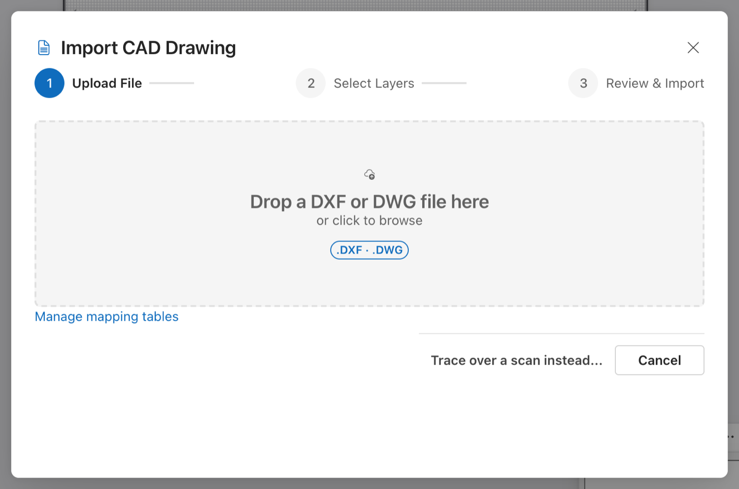
- In the Draw toolbar, click Expand Ribbon, find the Import / Export group, and click the upload button (tooltip Import CAD Drawing, "DWG or DXF"). The dialog is titled Import CAD Drawing. (A project's own page also has an Import DXF button that opens Draw on this dialog, and the Import drawing quick action on Home creates a new drawing in the project you pick and opens it on this dialog.)
- Drop your file on the "Drop a DXF or DWG file here" zone, or click it to browse. The dialog accepts
.dxfand.dwg.
What happens next depends on the file type, because the two formats take different routes:
| File | Route | Steps |
|---|---|---|
.dxf | Parsed in your browser | Upload File → Select Layers → Review & Import |
.dwg | Parsed on the server | Upload File → Map Blocks → Review & Import |
3a. DWG — the server route
DWG is a binary format the in-browser parser cannot read, so a DWG is uploaded and read on the server, then placed on your canvas in one write. The server reads DWG natively — it is not converted to DXF first, so nothing is lost or renamed in a conversion step.
After the upload, the step reads Uploading and reading the drawing on the server… while it works. Then two counters appear: Blocks found and Layers.
Below them is the Treat imported equipment as choice (Existing — retained by default; see Part 4) and the Block mapping table field, with the hint "Maps the drawing's CAD blocks to library symbols. Preselected from the drawing's block names." This is auto-detect at work: the pipeline reads the block names out of your drawing, scores every mapping table you have against that list, and preselects the winner. Options are labelled with the score, e.g.
Our Standard Blocks — 84% match (recommended)
That percentage is the detector's figure for this drawing's block names against that table. It is not a product accuracy claim, and you are free to override the choice — the control is searchable, so type to narrow a long list.
No screenshot: this step belongs to the DWG route, which the capture environment could not run. The DXF route's equivalent, the Block Mappings tab, is shown in the next figure.
- Click Import. The step shows Mapping blocks, tracing pipes and placing symbols… All the network reads happen before anything is written to the canvas, so a failure mid-import never leaves you with half a drawing.
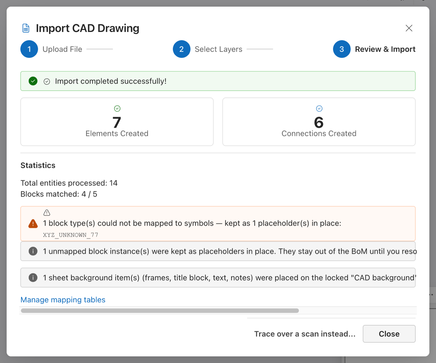
- The Review & Import step reports what landed:
| What you see | Meaning |
|---|---|
| Placed N symbols and M connections on the drawing. | Success. |
| The drawing was read, but no symbols could be placed with this mapping table. | The file parsed, but nothing matched. Go back and try a different table. |
| Blocks mapped / Blocks unmapped / Connections traced | The three counters for the run. |
| N low-confidence symbols were not placed. Check the drawing against the source. | Matches below the pipeline's confidence bar were counted but not placed. |
| N pipe run(s) could not be connected to a symbol. | Lines that traced but found no endpoint. |
One run per file. The pipeline stages its results against the upload, so the Import button fires once. If a run fails, the message ends "Go back and choose the file again to retry" — do exactly that rather than pressing Import again.
Below-threshold matches are dropped, not queued. A block whose match confidence falls below the bar is counted in the result step and left behind. There is no review grid on the CAD-import path where you can accept or correct those candidates one by one — so the N low-confidence symbols were not placed line is the only notice you get. The fix is either a better mapping rule (Part 2) or placing those few symbols by hand (Part 5).
3b. DXF — the in-browser route
A DXF is parsed in the browser, which gives you per-layer control the DWG route does not have.
After the parse ("Parsing DXF file…"), the Select Layers step offers three tabs:
Layers — the heading reads Select layers to import (n of m), with Select All and Clear buttons and a table of Layer Name against Entities. Click a row to toggle it. These are the layers searched for symbols and pipes. Sheet layers (layer 0, TITLE, BORDER, FRAME, SHEET) start unticked, and they still come across as sheet background (3d). Untick any other layer you do not want at all, such as revision clouds or dimension layers.
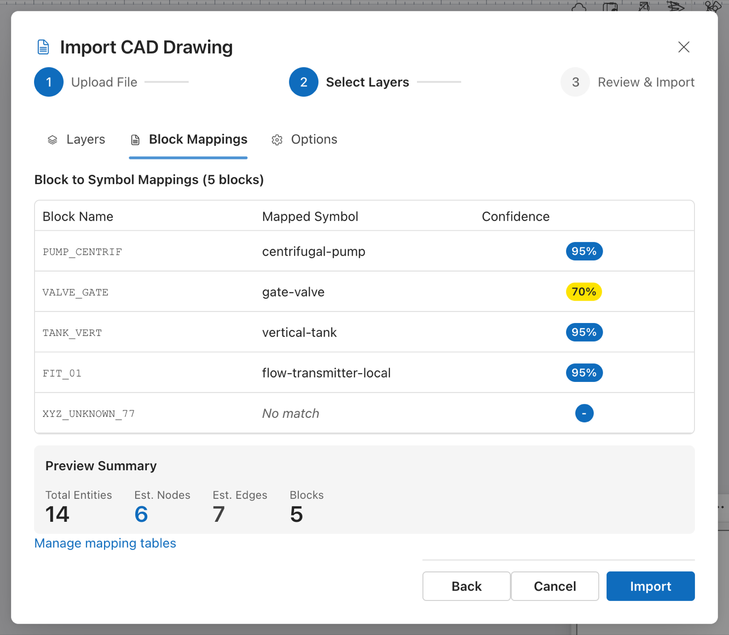
Block Mappings — Block to Symbol Mappings (n blocks), a table of Block Name, Mapped Symbol and Confidence. Blocks with nothing behind them read No match. Read this tab before importing: it is your preview of what the mapping rules will actually do, block by block.
Options —
| Option | Notes |
|---|---|
| Scale Factor | Multiplier applied to the imported geometry. |
| Origin X Offset / Origin Y Offset | Where the imported content lands on the canvas. |
| Flip Y-axis | On by default, and recommended — CAD and canvas disagree about which way Y runs. |
| Extract equipment tags from text | On by default. Picks up tag numbers from text entities near a symbol. |
| Auto-map blocks to symbol library | On by default. Turn it off to import geometry without symbol substitution. |
| Treat imported equipment as | Existing — retained (default), Existing — modified or New. Stamped as the asset status on every imported symbol, which is what the BoM reads. See Part 4. |
| Sheet background | Keep sheet background, Keep the title block and Fill the drawing's title-block fields, all on by default. See 3d. The DWG route has the same options on its Map Blocks step. |
A Preview Summary underneath shows Total Entities, Est. Nodes, Est. Edges and Blocks before you commit.
Click Import, then read the Review & Import step.
3c. Resolve the unmapped blocks
On both routes, a block the mapping could not match is kept on the drawing as a placeholder, not dropped: a dashed box labelled with the block name, at the block's exact position and rotation. It carries the block name and its attributes, and it stays out of the Bill of Materials until you resolve it — the BoM never counts something it cannot name. The Review & Import step says how many placeholders were kept.
Close the import dialog (or click Resolve CAD blocks… in the result step) and the Resolve CAD blocks panel opens. You can open it again at any time from Tools → Resolve CAD blocks….
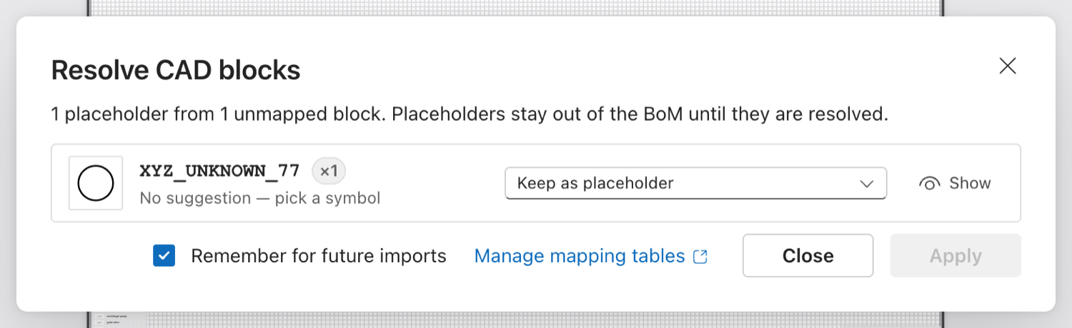
The panel lists each unmapped block name once:
| Column | What it shows |
|---|---|
| Preview | The block's own geometry (DXF route) or the placeholder, and the symbol it will become. |
| Block name and ×N | The CAD block name and how many instances of it are on the drawing. |
| Suggested: … | ErgoPlanner's guess from the block name and its descriptive attributes, by matching words against the symbol library — VALVE_GATE → Gate valve, PUMP_CENT → Centrifugal pump. Common CAD shorthand (VLV, CENT, GV, TK …) is expanded. A name that shares no word with any symbol gets no suggestion. |
| Symbol | A searchable list of the symbol library, defaulting to the suggestion, plus Keep as placeholder and Ignore (delete instances). |
| Show | Selects every instance of that block and frames them on the canvas. |
Pick a symbol per block name and click Apply. All choices are applied at once, as one undo step:
- A symbol — every instance is replaced in place: same position, rotation, layer and tag, with its CAD attributes and its asset status kept. Pipes that ended at the placeholder are re-attached to the new symbol. The replaced symbols enter the BoM on the next save.
- Keep as placeholder — nothing changes; resolve it later.
- Ignore (delete instances) — every instance is deleted, with its pipes.
Remember for future imports is ticked by default. It writes one rule per resolved block name — that exact name → the symbol you chose — into your company's mapping table, <company> CAD mappings. If that table does not exist yet, the panel creates it from the table the import used (built-in tables are read-only, so their rules are copied into the new table and your rules are added on top). Your rules outrank the built-in patterns, so on the next import the block maps automatically: on the DWG route auto-detect now recommends your table, and on the DXF route the browser reads your exact-name rules before its own patterns. To change or remove a learned rule, open Manage mapping tables.
3d. The rest of the sheet comes too
So that the imported drawing looks like the original, both routes keep everything that is not a symbol, a pipe or a tag: the drawing frame, the title block, notes and other text, loose linework, arcs, circles, hatch outlines and dimension text. Each item keeps its CAD layer name, colour, line weight and text size. It all lands as drawn shapes and text on a new CAD background layer, which is locked. Clicking, dragging and the eraser pass straight through it to the plant you are working on. Open View → Show Layers Panel to unlock or hide it.
The title block is found by its block name (TITLE, BORDER, FRAME or a TB name), or else as the attributed block in the frame's lower-right corner. Its drawing number, title, revision and date go into the open sheet's own title block. The Review & Import step says how many background items were placed and which title-block fields were filled.
None of this is in the Bill of Materials or the tag register, because none of it is a symbol. Untick Keep sheet background if you want the engineering content only.
3e. Only a PDF from CAD? Import it as vectors
If the CAD file is gone but you have the PDF that was plotted from it, drop the PDF into the same Import CAD Drawing dialog (the badge reads PDF (vector, from CAD)).
- On Scale & Suggest, check the summary (paper size, vector paths, text runs) and pick the Page of a multi-page PDF.
- Set Scale to mm. Paper size (1:1) is right for a sheet you will keep at its paper size. For a drawing plotted to scale, use Drawing scale 1:N, or Two known points and click two points whose real distance you know.
- Leave Suggest symbols from tag text ticked and click Import.
The linework and text land on the locked CAD background layer, and the title block's labelled fields fill the sheet's title block. Every tag such as P-101, V-201 or FT-301 becomes a placeholder at its position, grouped by prefix (P-* pump). Close the dialog and map the groups in Resolve CAD blocks (3c): one choice per prefix replaces every placeholder in the group, and each symbol keeps its tag. A PDF has no pipe topology, so draw the pipes over the background.
If the PDF turns out to be a scan, the dialog says so and offers Open as reference overlay, which is Part 4b with the file already loaded.
3f. Make the sheet a reusable template in one go
When the imported sheet is a standard arrangement you will reuse, click Import as template on the dialog's last step instead of Close (or start with Tools → Import as template…). Resolve the blocks when the panel opens and click Apply. If any placeholder is still unresolved, a message says how many and reopens the panel. The Create Template from Selection wizard then opens with the title block's title as the name. Save puts the template in your library with everything the import placed, and with the sheet background as locked decoration that is never in the Bill of Materials. See Drawing Templates: Import as template.
Part 4 — Separate existing from new
Your imported plant is on the canvas as native elements. Before you add anything, make the existing plant distinguishable from the work you are about to design. Three mechanisms, all real, do different jobs:
Put existing and new in different model areas
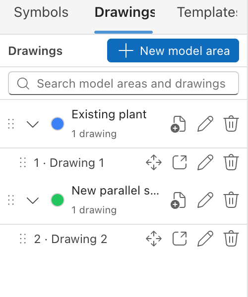
In the left panel, switch to the Drawings tab. It is a tree of model areas, each holding drawings (sheets), with an Unassigned group for anything not filed yet.
- Create an area — Title (required, e.g. Existing plant), Description, Tags and a Colour.
- Create a second one for the new work (e.g. New parallel stream).
- Move your imported sheet into the existing-plant area, and put new sheets in the other.
This matters downstream: BoM line items carry their area and sheet, and the BoM detail view filters by them. Filing the import into its own area is what later lets you read the new work's quantities apart from the existing plant's.
Use the existing-retained line type on existing pipework
The Line Type dropdown in the Draw toolbar includes two line types for exactly this:
| Line type | Appearance |
|---|---|
| Existing Retained | Thin black, dash-dot-dash |
| Future Provision | Thin grey, widely dashed |
Select the imported pipe runs and set them to Existing Retained. They now read as existing plant on the sheet, to the same convention a draughtsperson would use by hand. The full line-type list is in Drawing and Connecting.
Tag it
Use the drawing's and the area's Tags fields for anything you will want to filter or search on later — existing, phase 1, retained.
How the BoM splits existing from new. Every BoM line has an asset status: New, Existing — Modified, Existing — Retained or To be removed. The CAD import now sets it for you: the import dialog's Treat imported equipment as choice (default Existing — retained) is stamped on every symbol it places, and with Existing — retained the imported pipe runs are given the Existing Retained line type too (a run that already has a specific line type, such as a utility air line, keeps it). Pick New if you are importing a design rather than a survey. To change one element afterwards, select it and use Asset status in the properties panel, or set the status on the line in the BoM. The BoM shows a Procurement total that counts only New and Existing — Modified lines, next to the gross total. See Asset status.
Part 4b — No CAD source? Trace over a scan
When all you have is a scanned P&ID (a PDF plotted from CAD imports as vectors, see 3e), put it behind the drawing and trace over it.
- Choose Insert -> Reference image... (or, in the CAD import dialog, Trace over a scan instead...).
- Drop a PDF, PNG, JPG or WebP. For a PDF, pick the page and press Load page; it is rendered in your browser and nothing is uploaded.
- Set the scale. Under Scale Mode choose Two known points, click two points on the preview whose real distance you know (two nozzles, a dimensioned run), and enter that distance in millimetres. The drawing is scaled so those two points are exactly that far apart.
- Set Opacity so you can see both the scan and your work, and leave Lock to canvas on once it is aligned. Unlock it to nudge or resize; it can also be frozen from the Layers panel.
- Click Apply Background and place symbols and connections over the scan.
The reference image is stored with the drawing (one per drawing; a new one replaces it), so it is still there after a reload. It is never a symbol, so it does not appear in the Bill of Materials and is not part of the drawing's element model. See Background Images.
Part 5 — Add the new work
With the existing plant in place and marked up, design the additions the same way a greenfield project does:
- Place templates for whole new process areas — left panel Templates tab, Configure, then Drag to Place on Canvas. See A Greenfield Project, Part 3.
- Or describe the new areas to the AI Assistant and work the composition plan it returns. See A Greenfield Project, Part 4.
- Connect new to existing with the Connector tool (
K). An interface between an existing header and a new one is an ordinary connection on the drawing — nothing special is needed to cross the boundary. - Fill the gaps by hand. Anything the import did not capture — a non-standard block, a hand-drawn annotation, a low-confidence symbol that was held back — is placed from the Symbols stencil like any other symbol.
Then run the Validation panel and clear its errors before you go on (Server-Side Validation).
Part 6 — The Bill of Materials
The BoM is generated from the drawing and re-synced on every save, so your imported elements are already in it.
- Open it from the ribbon's Import / Export group — Bill of Materials (BoQ, Line List) — or from Bill of Materials on the sidebar (
/admin/bom). - Use the area filter to read the new work's quantities on their own, then the existing plant's.
- Export CSV in the BoM list's command bar downloads what your filters currently show, as
bom-export.csv.
If the import arrived in bulk and you want a clean regeneration, use Generate BOM in the BoM list's command bar rather than waiting for a save. Everything else about the BoM — statuses, overrides, per-item detail — is in Bill of Materials.
Things worth knowing
- DWG goes through the server; DXF does not. That is why the DXF route offers layer selection and scale/origin options and the DWG route offers a scored mapping table instead. If you need per-layer control over a DWG, export it to DXF from your CAD system first.
- Auto-detect scores tables, not drawings. The percentage beside a mapping table is how well that table's rules cover the block names in the file you just uploaded. A low score across all your tables means your CAD library is not described yet — go and write rules (Part 2).
- The mapping learns what you resolve, and only that. Every block you resolve in the Resolve CAD blocks panel with Remember for future imports ticked becomes an exact-name rule in your company's table. It does not guess rules on its own, and a block you keep as a placeholder or ignore teaches it nothing.
- Custom tables are saved per company. They live in the database and survive restarts; use Export as JSON to share one outside your company.
- The sheet comes across as locked background. Frame, title block, notes and loose linework land on the locked CAD background layer, outside the BoM. Unlock that layer to edit them.
- Unmapped blocks are kept, not dropped. Each one stays on the drawing as a placeholder at its exact position, out of the BoM until you resolve it. The Blocks unmapped counter and the DXF No match rows tell you how many there are before you import.
- Low-confidence matches are discarded, and there is nowhere to review them. When the result step says N low-confidence symbols were not placed, compare the canvas against your source before building on it — nothing is held in a queue for you.
- A failed import leaves nothing behind. The import writes to the canvas once, after every read has succeeded.
Where to go next
- Issuing a Drawing — freeze a revision and send a transmittal
- Running a Design Review — the comment lifecycle
- A Revision Cycle — Rev A → Rev B and the stage gate
See also
- A Greenfield Project, End to End — the from-nothing route
- Importing a P&ID — the raster/scan route, and its limits
- Background Images — using a legacy drawing as a visual reference to trace over, when there is no CAD source at all