What is an intelligent P&ID?
What the term means for an engineer, and how to get one.
Comparisons of this kind usually run on adjectives. These are five questions you can put to a drawing you already have, this afternoon.
| Put this to the drawing | A CAD drawing | An intelligent P&ID |
|---|---|---|
| How many DN100 gate valves are on this sheet? | Count them by eye, or trust the last count. | A query over the elements and their attributes. |
| What feeds this tank? | Follow the line across the sheet yourself. | Connections are directed, so upstream is a traversal. |
| Swap a pump for a bigger one. | Erase, redraw, then find every other sheet it is on. | Change the element; the sheets are views of it. |
| Where did this bill-of-materials line come from? | Someone typed it. The link is in their head. | The line carries the id and tag of its element. |
| What do you own at the end? | A file, and whoever can open it. | A structure the drawing is one view of. |
The short answer
A P&ID records two things: what a plant is made of, and how it is connected. The vessels, pumps, valves and instruments; the lines between them; and the tag that names each one.
On a CAD drawing that record lives in the eye of the reader. The file holds lines, arcs and text. A pump is a group of strokes a person recognises as a pump, and the tag beside it is text that happens to sit nearby. Nothing in the file knows the two belong together, or where the line leaving the pump arrives.
On an intelligent P&ID each of those is an object. The pump is an element with its own identity, a tag and a set of attributes. The line is a connection with a direction, a source and a target. The sheet you look at is a view of that structure rather than a picture kept alongside it.
That is the whole distinction. Everything sold on top of it — quantities that count themselves, registers that cannot disagree with the drawing — follows from it.
What makes an element “intelligent”
Four properties. None of them is a feature anyone sells; they are the shape of the data, and everything else is downstream of them.
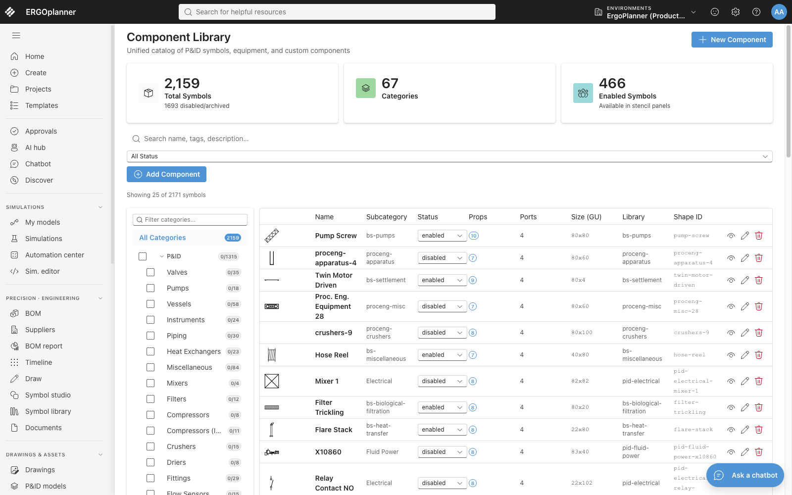
Every symbol definition in the catalogue carries a property count, a port count and a size in grid units. Place one twice and you have two objects with two sets of values — not two copies of a picture.
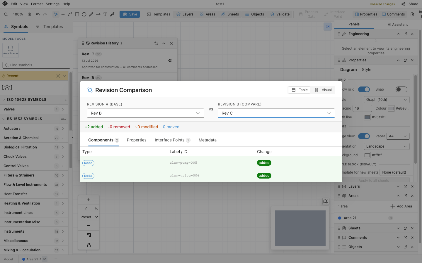
Comparing two revisions returns elements, not pixels: two nodes added, named by their own ids, with separate tabs for properties and interface points. A drawing made of lines can only tell you that the picture is different.
The phrase you will hear, and what it is worth
Vendors call this a digital source of truth, and the phrase has one honest meaning: the drawing is not a document kept alongside a database and reconciled with it, it is a view of that database.
What it never says is how much of the plant is in there. That is the question worth putting to anyone who uses it, ours included — which elements carry attributes, which deliverables are derived from them, and which are still typed by a person. Ask for the second list.
What you get for the extra discipline
Structuring a drawing costs more up front than drawing it. These are the four things the structure pays for, each narrowed to what the software actually does today.
Two ways to end up with one
- Upload
- The pipeline proposes
- You accept or reject
- Placed in the model
One thing to know before you plan a round tripDWG comes in and does not go out. Sheets export as PDF, SVG or PNG, and as DXF for one sheet or a whole set. There is no DWG writer.
Where to go from here
The fast way to settle whether any of this is real is to look at the editor. The slower way is to read what each part of it does, and what it does not.