P&IDs that are a view of your model
Place from a standards library, tag it once, and every sheet stays the same drawing.
Try it with a sample plant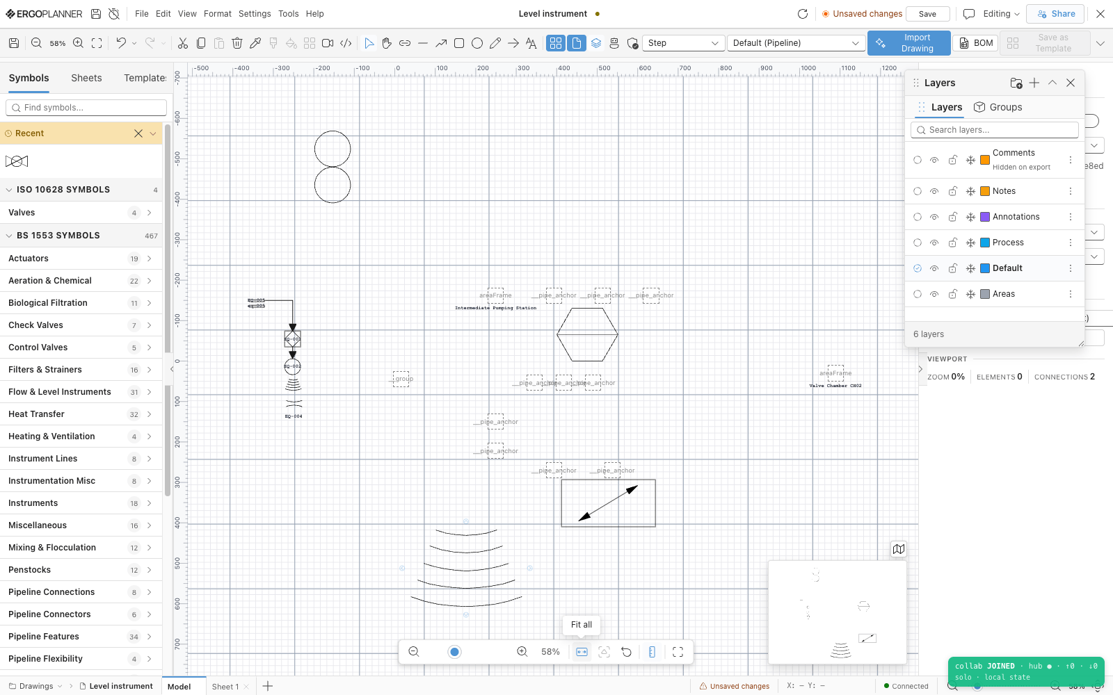
What this replaces
The same change redrawn on five sheets, because each sheet is its own file
Nobody can say which drawing is current without asking the person who issued it
A symbol library that drifts from the standard the client asked for
How it works
What you get out
- Drawing sheets as PDF, SVG or PNG
- DXF — one sheet or a multi-sheet set
- Tag register (CSV)
- Version register (CSV or JSON)
- Drawing register — on screen, one row per process-area view; no file export yet
Drawings, registers and exports are produced from your model as you build it. They are working engineering documents and need a competent engineer’s review before they are issued.
What it is built to
- BS 1553 — symbol library
- ISA-5.1 — symbol library, and the tag-format validation rule
- ISO 10628 — symbol library
- PIP — symbol library
- IEC — symbol library
Technical capabilities
Questions people actually ask
Is a sheet a file?
No. A sheet is a view with bounds and a title block over the one model, and so is a process area. That is the whole point of the page: there is no copy of the pump on sheet 3 to forget to update, because sheet 3 is a window, not a document.
Can I export to DWG?
Not today. You can export DXF — a single sheet or a multi-sheet set — and PDF, SVG or PNG. DWG works in the other direction: you can import a DWG and we will read it. If DWG export decides a purchase for you, tell us, because that is the kind of thing that gets built.
Which standard do the symbols follow?
Each symbol is filed under the standard its library came from — BS 1553, ISA-5.1, ISO 10628, PIP or IEC — and you pick which library you draw from. Rendering one model against a second standard is a Professional-plan capability.
Does it check my drawing against the standard?
It checks what it can check mechanically: tag format against ISA-5.1, and duplicate tags. It does not decide whether a symbol is the right symbol under BS 1553 or ISO 10628 — that is still a competent engineer’s call, and we would rather say so than imply a compliance check we have not written.
What happens to a drawing I imported from CAD?
It is mapped, not recognised: each block in a DXF or DWG is matched against your mapping table and becomes a tagged element, and blocks with no mapping are kept as placeholders for you to resolve. A scan or PDF goes through recognition instead, and you review every proposed symbol before anything is placed. Import & Recognition has the detail.